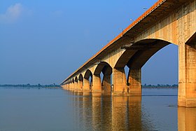
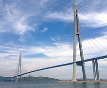
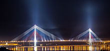
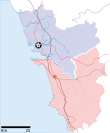
The Mandovi Bridge is a bridge between towns Panaji and Porvorim, in Goa. It carries the NH 17 over the tidal part of the Mandovi River. The first and second bridge are multiple span beam bridges and the third is a cable-stayed bridge which is under construction. It has a total length of 3,771 metres. The Mandovi bridge is one of the most famous bridge and longest bridge in Goa. Before the bridge was built, the ferry was the main mode of transport across River Mandovi well into the 1970s between Panaji and Betim village. Due to heavy traffic the first bridge was built in the 1970s. Later in 1986 the first bridge collapsed and was later rebuilt. The second bridge was constructed in 1998 in order to accommodate heavy transport vehicles. The third bridge is under construction which began in 2014. The reason for the third cable-stayed bridge is to accommodate heavy traffic especially during the peak year end tourist season. Larsen and Toubro (L&T) were awarded the EPC contract at a bid of `24.24 crore to build and design the third bridge.
Prime minister Narendra Modi will inaugurate the third Mandovi bridge in August, even while the bridge itself is expected to be completed during the June-July period. The prime minister may also lay the foundation stone for a convention center at Dona Paula during his Goa visit. “The prime minister has agreed in principle to visit Goa to inaugurate the bridge. I told him that the construction of the bridge will be completed in June-July,” chief minister Parrikar said. He also clarified that the actual date in August when the PM will throw open the bridge has not been fixed. Earlier, GSIDC had said that the bridge would be commissioned in May 2018.
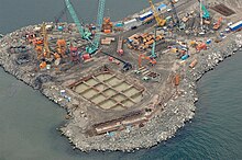
Foundation being laid
Sticked To His Commitment For Infrastructure Narendra Modi Today Laid the Foundation Stone of the New Mandovi bridge at Goa on June 14, 2014.Speaking on the occasion, P M Modi said Goa is one of the key areas for development of tourism in India. And the first requirement for developing tourism is good infrastructure. He Said That Good infrastructure can boost the Indian economy, The Prime Minister said people’s expectations of infrastructure too, had changed over time. The people of India, today, want good quality of infrastructure.
Design in Focus: Cable Stayed Bridge
A cable-stayed bridge has one or more towers (or pylons), from which cables support the bridge deck. A distinctive feature are the cables which run directly from the tower to the deck, normally forming a fan-like pattern or a series of parallel lines. This is in contrast to the modern suspension bridge, where the cables supporting the deck are suspended vertically from the main cable, anchored at both ends of the bridge and running between the towers. The cable-stayed bridge is optimal for spans longer than cantilever bridges and shorter than suspension bridges. This is the range where cantilever bridges would rapidly grow heavier if the span were lengthened, while suspension bridge cabling would not be more economical if the span were shortened.
Cable-stayed bridges have been known since the 16th century and used widely since the 19th. Early examples often combined features from both the cable-stayed and suspension designs, including the famous Brooklyn Bridge. The design fell from favor through the 20th century as larger gaps were bridged using pure suspension designs, and shorter ones using various systems built of reinforced concrete. It once again rose to prominence in the later 20th century when the combination of new materials, larger construction machinery, and the need to replace older bridges all lowered the relative price of these designs.
Comparison with suspension bridge
Cable-stayed bridges may appear to be similar to suspension bridges, but in fact, they are quite different in principle and in their construction.
In suspension bridges, large main cables (normally two) hang between the towers and are anchored at each end to the ground. This can be difficult to implement when ground conditions are poor. The main cables, which are free to move on bearings in the towers, bear the load of the bridge deck. Before the deck is installed, the cables are under tension from their own weight. Along the main cables smaller cables or rods connect to the bridge deck, which is lifted in sections. As this is done, the tension in the cables increases, as it does with the live load of traffic crossing the bridge. The tension on the main cables is transferred to the ground at the anchorages and by downwards tug on the towers.
In the cable-stayed bridge, the towers are the primary load-bearing structures which transmit the bridge loads to the ground. A cantilever approach is often used to support the bridge deck near the towers, but lengths further from them are supported by cables running directly to the towers. This has the disadvantage, compared to the suspension bridge, that the cables pull to the sides as opposed to directly up, requiring the bridge deck to be stronger to resist the resulting horizontal compression loads; but has the advantage of not requiring firm anchorages to resist the horizontal pull of the main cables of the suspension bridge. By design all static horizontal forces of the cable-stayed bridge are balanced so that the supporting towers do not tend to tilt or slide, needing only to resist horizontal forces from the live loads.
Key advantages of the cable-stayed form are as follows:
- much greater stiffness than the suspension bridge, so that deformations of the deck under live loads are reduced
- can be constructed by cantilevering out from the tower the cables act both as temporary and permanent supports to the bridge deck
- for a symmetrical bridge (i.e. spans on either side of the tower are the same), the horizontal forces balance and large ground anchorages are not required
Design variation
There are four major classes of rigging on cable-stayed bridges: mono, harp, fan, and star.
The mono design uses a single cable from its towers and is one of the lesser-used examples of the class.
In the harp or parallel design, the cables are nearly parallel so that the height of their attachment to the tower is proportional to the distance from the tower to their mounting on the deck.
In the fan design, the cables all connect to or pass over the top of the towers. The fan design is structurally superior with a minimum moment applied to the towers, but, for practical reasons, the modified fan (also called the semi-fan) is preferred, especially where many cables are necessary. In the modified fan arrangement, the cables terminate near to the top of the tower but are spaced from each other sufficiently to allow better termination, improved environmental protection, and good access to individual cables for maintenance.
In the star design, another relatively rare design, the cables are spaced apart on the tower, like the harp design, but connect to one point or a number of closely spaced points on the deck.
There are also four arrangements for support columns: single, double, portal and A-shaped.
The single arrangement uses a single column for cable support, normally projecting through the center of the deck, but in some cases located on one side or the other.
The double arrangement places pairs of columns on both sides of the deck.
The portal is similar to the double arrangement but has a third member connecting the tops of the two columns to form a door-like shape or portal. This offers additional strength, especially against traverse loads.
The A-shaped design is similar in concept to the portal but achieves the same goal by angling the two columns towards each other to meet at the top, eliminating the need for the third member. The inverted Y design combines the A-shaped on the bottom with the single on top.
Depending on the design, the columns may be vertical or angled or curved relative to the bridge deck.
The importance of steel wire rope for the bridge
Wire rope is several strands of metal wire twisted into a helix forming a composite “rope”, in a pattern known as “laid rope”. Larger diameter wire rope consists of multiple strands of such laid rope in a pattern known as “cable laid”.
In stricter senses the term “wire rope” refers to diameter larger than 3/8 inch (9.52 mm), with smaller gauges designated cable or cords. Initially wrought iron wires were used, but today steel is the main material used for wire ropes.
Historically, wire rope evolved from wrought iron chains, which had a record of mechanical failure. While flaws in chain links or solid steel bars can lead to catastrophic failure, flaws in the wires making up a steel cable are less critical as the other wires easily take up the load. While friction between the individual wires and strands causes wear over the life of the rope, it also helps to compensate for minor failures in the short run.
Wire ropes were developed starting with mining hoist applications in the 1830s. Wire ropes are used dynamically for lifting and hoisting in cranes and elevators, and for transmission of mechanical power. Wire rope is also used to transmit force in mechanisms, such as a Bowden cable or the control surfaces of an airplane connected to levers and pedals in the cockpit. Only aircraft cables have WSC (wire strand core). Also, aircraft cables are available in smaller diameters than wire rope. For example, aircraft cables are available in 3/64 in. diameter while most wire ropes begin at a 1/4 in. diameter. Static wire ropes are used to support structures such as suspension bridges or as guy wires to support towers. An aerial tramway relies on wire rope to support and move cargo overhead.
The design history behind the Mandovi Bridge
The Mandovi River Bridge was Russian in design and the first to be used in this country. The first Mandovi bridge was built in the 1971 and the second one in 1998. On 5 July 1986 the first bridge collapsed. After the collapse, this project required the dismantling of the old bridge structure and strengthening with by filling M20 concrete. The total cost of construction was `2 crores. The parallel bridges have a length of 600 metres each. Both bridges carry one way traffic.
Third cable-stayed bridge
On 14 June 2014, the foundation stone for the third Mandovi bridge was laid by Indian Prime Minister Narendra Modi. The third bridge will be cable stayed bridge constructed between the first and second parallel bridges which will be spanning over 3 kilometers and would be 15 meters higher than the existing two bridges. The third bridge will be designed and constructed by Larsen & Toubro (L&T). The bridge will be a 900 m four lane bridge will be a 550 m cable stay portion and a 3.2 km viaduct approach. The main bridge is 600m in length with two end spans of 75m and three interior spans of 150m. The main bridge superstructure consists of 21m wide externally strutted segmental concrete box girder with dual carriageway of 2 x 8.5m with 3m wide median at the centre. The box girder will be supported by stay cables which will be anchored in the pylon and stressed from box girder bottom. Another flyover arising from the Merces-Old Goa bypass road will join the Mandovi bridge for traffic from Ponda to go towards Margao. The revised cost of construction of the particular bridge being built is `860 crore and the cost could increase by `50 crore.
During the laying of the foundation stone, Government of Goa claimed that the bridge would be funded independently. The loan agreement was signed on 8 June 2015 between National Bank for Agriculture and Rural Development(NABARD) and the nodal agency granted a loan amount of `462.60 crore. The original cost of bridge was estimated to be `470 crore and has risen up to `860 crore. With a repayment period of 12 years. the government is supposed to pay an interest of `48 crores annually with regards to the Mandovi Bridge loan. The total amount to be repaid NABARD by the end of June 2027, therefore, stands at a figure of `866.44 crore. This bridge is set to be the most expensive bridge in Goan history.
The Incharge:
In 2004 it was reported that L&T Construction bagged new orders worth `2,002 crore across various business segments during June. The heavy civil infrastructure segment secured orders worth `1,547 crore, which includes an order from Goa State Infrastructure Development Corporation for the design and construction of a cable stayed bridge across river Mandovi at Panaji, the company said in a statement. It is a 900m four-lane bridge, with a 550 m cable stay portion and a 3.2 km viaduct approach. The power transmission business has bagged orders worth `392 crore in both domestic and international markets.
The domestic order is from the Bihar State Power Transmission Company Limited for a turnkey construction of a new 220 /132 kV transmission line between Kanti-Motipur-Muzaffarpur-Bhikanpura in Bihar, the company said. It added that its wholly-owned subsidiary L&T Saudi Arabia has bagged a key international engineering, procurement and construction order of a high voltage substation network for a major fertiliser company in Saudi Arabia. Additional orders have also been received from an ongoing job of water and renewable energy Business, it said.
The system analysis of the Mandovi bridge:
The foundation stone for the third bridge, which would be the largest bridge in Goa, was laid by Prime Minister Narendra Modi which would span 3 km and would be 15 meters higher than the existing bridges spaced in between the two. The new bridge is expected to be completed within 30 months. According to the sources from GSIDC “Almost 66,000 vehicles travel over the existing Mandovi bridges every day, At least 25,000 of these will go over the new bridge directly to Margao or Ponda once it is built. This is expected to greatly reduce the present traffic congestion near the Panaji KTC bus stand.”
The main bridge is 600m in length with two end spans of 75m and three interior spans of 150m. The main bridge superstructure consists of 21m wide externally strutted segmental concrete box girder with dual carriageway of 2 x 8.5m with 3m wide median at the centre. The box girder will be supported by stay cables which will be anchored in the pylon and stressed from box girder bottom. The total length of the new bridge will be 3.19km. It will start near the Pundalik Nagar junction at Porvorim and end near the Merces junction. The highlights of this 900m four lane bridge will be a 550 m cable stay portion and a 3.2 km viaduct approach.
Objection
The construction of the third bridge was challenged by Goa Foundation alleging that it is being constructed without an Environment Clearance. It also challenged the destruction of some 247 mangrove trees for constructing ramps to access the bridge. According to the Goa State Infrastructure Development Corporation’s Environment Impact Assessment (EIA) report as requested by National Green Tribunal, the construction of third Mandovi bridge will destroy mangroves to a certain extent and also impact marine ecology. The EIA also stated that there will be no loss to flora and fauna and other vegetation. However the mangroves will be replaced at suitable sites identified by Forest Department and marine ecology will be restored as stated by the EIA.
The present state
There has been slight up and down segmentation for the bridge construction. There has been slight speed variation in the completion of project. As of dec 2017, around 68 percent work was completed.
While on the overall, 68% progress has been made on the new Mandovi bridge till November-end, the entire work is expected to be completed by May 31, 2018, said chief minister Manohar Parrikar in a written reply to the Goa legislative assembly said. Ponda MLA Ravi Naik tabled the question seeking to know the current status of the project. a detailed reply, Parrikar informed the house that till date, 455 piles out of 465 (72 in the river and 383 on land) and 76 pile caps out of 94 (four in the river and 72 on land) have been completed. Also, 65 piers out of 94 have been cast for the viaduct portion on the northern side and at the southern portion.
Of the 1227 bridge segments, 452 have been cast, 155 segments of four -lane portion have been erected on North side and all pylons below the deck have been completed, Parrikar said. As many as 48 segments for the main bridge have been erected and the erection of 11 pairs of stay cables has been completed. Also, the casting of bridge portion (from RA01 to RA06) is completed while RA06 to RA07, on the south side, at the Merces circle, is in progress, Parrikar said in a reply.
As of Feb of 2018, 78 percent was deemed complete with only seven piles remaining to be completed, according to the Goa state infrastructure development corporation (GSIDC). Of the 465 piles, 458 are ready, comprising 72 in the Mandovi river and 386 on land. The bridge’s deadline has been set for May 2018, the third date fixed for the project’s completion. Following the completion of the installation of the stay cables for the third Mandovi bridge, GSIDC has now also started connecting the stay cables for the pylon that have been constructed on the river bed.
construction photographs
| Mandovi Bridge |
|---|

Mandovi bridge as seen from Panaji jetty |
| Carries | Four lanes of NH 17 |
|---|
| Crosses | Mandovi River |
|---|
| Characteristics |
|---|
| Total length | 600 metres (2,000 ft) each |
|---|
| History |
|---|
| Opened | 1971 (first)
1998 (second) |
|---|
| Collapsed | 5 July 1986 (rebuilt) |
|---|


